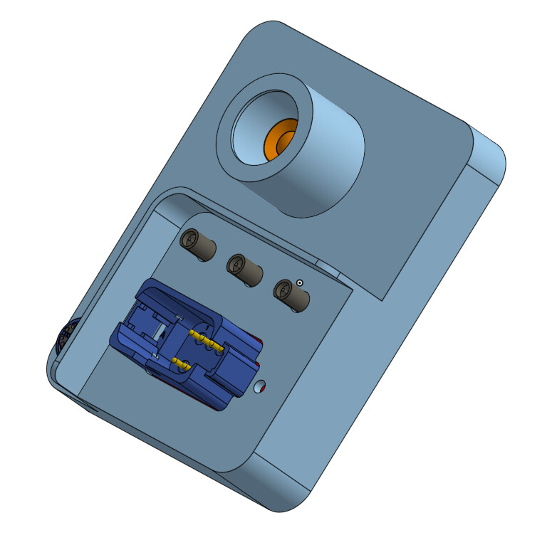
We’ve been working on the OWL3.0 for a while and I wanted to share some progress to keep you in the loop. It’s a single-board design based around the Raspberry Pi CM5 within a machined aluminium enclosure. The aim is to improve performance, quality, ruggedness, ease of mounting and flexibility of the unit. Plus a lot of more features.
The custom board and enclosure idea give us some advantages:
No screw terminals or internal wiring required. Wiring and crimp connections leave room for error and slow down the production process. This approach makes assembly simpler and the final device more reliable in the field.
The Amphenol AT13 12pin plug is a much more common find on farms/equipment. It makes it easier to source/work with if it exists on existing machinery.
An aluminium enclosure avoids the need for an internal fan, by dissipating heat through the case and into any mount. The Pi 5 fan works at managing heat, and we haven’t had any failures yet, but moving parts in systems meant for use in harsh environments is not ideal.
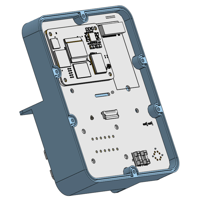
We can add many more features in an enclosed, smaller space, without the need for stacking so many Pi HATs and using such a large enclosure. This was a major limitation before. The new board will have: CM5, NB-IoT + GNSS module, WiFi/Bluetooth, IMX296 camera in the M12 version, an M.2 slot for the Hailo accelerator or SSD and an external ethernet port.
It can be a lot smaller (120 x 100mm) than using off-the-shelf enclosures at a similar manufacturing cost. We’re hoping that even with the customisation and extra features, this should end up either cheaper or about the same price as purchasing all the other components with a Pi 5.
There are many redundant parts on a Pi 5 that add to the weight/error. This way we can control exactly what we need.
Each unit will now have NB IoT and GNSS if needed - makes fleet management/remote access and debugging easier.
It’s not perfect, and very much open to input from you if you think changes could improve it. Full credit to @blinken for all the design work with this.
Designs will be open sourced as usual once we’re happy with it and we’ll try getting out a 3D printable enclosure to go alongside this so you don’t have to use a machined aluminium version, which can add cost. The plan is also to begin selling these in kits in 2026, so stay tuned and let us know if you’re interested.
The other designs will continue to be supported - there are a lot of advantages to working with Pi HATs, and having a custom board does make this less accessible in a sense that buying/having a board made is required. Whereas truly off-the-shelf builds using mass produced components can be beneficial in some settings (although scale/reliability do suffer).
In any case, I’ll keep you updated here as prototypes come in. Very much welcome any input/feedback on the design.
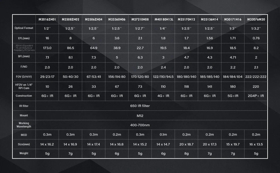
We’ll fit them with a 60 degree lens, so when mounted at 500mm they’ll have a 1m wide view. The lens is changeable though for different mounting arrangements.
We had some good success mounting in line with the spray line at a 15 degree forward angle, in our 12m version to avoid adding the 30cm+ of horizontal needed when facing straight down. I’ll also design a stainless mount to keep them at 15 degrees.
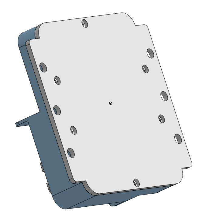
One thing I’m not sure about is what mounting setup is best/most versatile. M8 U bolts? The backplate on the design above has 6x M6 holes.
As for lighting, I did consider adding a 10A switched line for easy connection of lights, but it complicates the board a little if you need a 20A input. So it will be something DIY at this stage.
Just to make sure, with a 60 degree lens and at 500 mm (pointing straight down) I don’t think the view is 1 m (it will be 577 mm). You need 90 degrees for 1000 mm at 500 mm height. Unless you put them at an angle as you said.
Have you looked at different lens w.r.t. to F value and megapixels and if those make any significant difference?
When you say 10 A or 20 A for lighting this seems quite high. I believe to put a 50-70W LED flood light you probably need ~3 A.
with a 60 degree lens and at 500 mm (pointing straight down) I don’t think the view is 1 m (it will be 577 mm). You need 90 degrees for 1000 mm at 500 mm height. Unless you put them at an angle as you said.
That’s a good pickup, I was being a bit lazy with the writing and using the claimed HFOV from Arducam. I tested it yesterday at 500mm and the HFOV is roughly 1000mm, so as needed. The call it a 60 degree lens (it’s actually 67 degrees from their documentation) but that is based on a 1/4" RPi camera, whereas the IMX296 is a 1/2.9", hence the difference. Thanks for pointing it out though! The forward angle helps of course. We found more false positives on the edges from this lens, so added a 2% buffer around the image that is removed. This fixed that issue.
These lenses claim 5MP with an F number of 2, so they should suit the IMX296 quite well. I would assume more expensive lenses would improve image quality somewhat and I have tried some Tamron and Fujinon adjustable focus lenses on the official C-mount Raspberry Pi Global Shutter and the image quality was possibly better? Not too sure and I didn’t run any tests. I think the IMX296 is the limiting factor here in any case, given it is only 1.58 MP, though has large pixel size (3.45 x 3.45 um). The AR0234 is a logical upgrade, but drivers not as accessible. We did look at the quality of different cameras a while back but this was pre RPi IMX296 days. Arducam AR0234 was very good though.
When you say 10 A or 20 A for lighting this seems quite high. I believe to put a 50-70W LED flood light you probably need ~3 A.
In the past we tried lower wattage LED lights and we found they didn’t quite work for night time use. >90W @ 12V was much better. 10A is probably a little overkill, but supporting 120W light would be nice. What do you think though? How essential would it be to have a light switch/connector integrated into the board? Adding a ring light inside the enclosure would be too much, but is it worthwhile have switched pins there? Otherwise you would just need to add your own lighting loom in.
edit: one thing I’ll add is that you can move up into the >3MP machine vision cameras, but you add $$$ to the cost. It is beneficial for data collection, and we hope to build a machine vision, data collection OWL (without actuation) but this would be for data collection not spot spraying.
I haven’t done nearly as much field testing as you have, but I am seeing that in high contrast cases (e.g. bright light and weed in the shade) it might not be able to pick up the green. I am testing some LED lights and I’ve made a couple of observations:
You lighting should be just “flood” and shouldn’t have any “spot” elements, because the spot elements create bright spots, which creates high contrast shade-like areas.
You probably need a source of at least 50-60 Watts. I have to do more testing on this because I am not sure it can compensate shades in bright direct sunlight.
It looks like it’s better to use 2x30Watts to distribute the light better, than one 60Watt LED light.
High contrast is one of the biggest challenges in bright sun - even expensive machine vision cameras really struggle from experience.
Oh that’s really interesting/useful. I would recommend more than 50/60 watts to manage the sun - I would say 2 x 50W would be better. Many do strobes for this purpose, but they are much more expensive/difficult to get working correctly.
Turns out we will have a 10A set of pins on the board, but they won’t be exposed in our aluminium case.
I’m not an expert but I found those ampseal plugs a pain to wire up. Probably fine with practice.
I used binder 720 series for a project. 3-12 pins, high amps (7a) for their size and ip67. Easy to use, easy to wire and readily available from online suppliers. Maybe not common on farms ( I’m not sure where they’re used ).
Edit: looks like the current rating drops off with more pins, Not sure what you need..
Thanks for sharing, they look quite nice and I haven’t come across them before. Connector choice is probably one of the most challenging parts of this build!
I can’t say I have crimped many of these DT-style fittings, though I have done hundreds of the Amphenol fathomlock connectors before. They aren’t too bad and look similar. I’ve heard from farmers these DT-style plugs are very common and not too difficult to wire? It also seems to be a standard on 12V light fittings for vehicles alongside superseal 1.5 connectors.
The AT13/DT13 series is rated to 13A per pin, which gives us a safety factor for the 10A rated OWL. TE Connectivity and Amphenol make interchangeable components too plus many different knockoffs.
So some of the decision make around this choice was focused on interoperability + ecosystem support/tools on hand. Will definitely keep these Binder 720 in mind though for other projects. Connectors are such a rabbit hole. Circular connectors have many advantages over square/rectangular style fittings and these look quality.
Definitely like these connectors, I will keep them in mind for future projects!
As @geezacoleman has stated, connector choice is always a challenge! I actually decided to use a standard cable gland with 18AWG-6 conductor cable as a pigtail to a standard DT 6 pin connector. Honestly I already had a bunch on hand due to its fairly standard use on ag equipment.
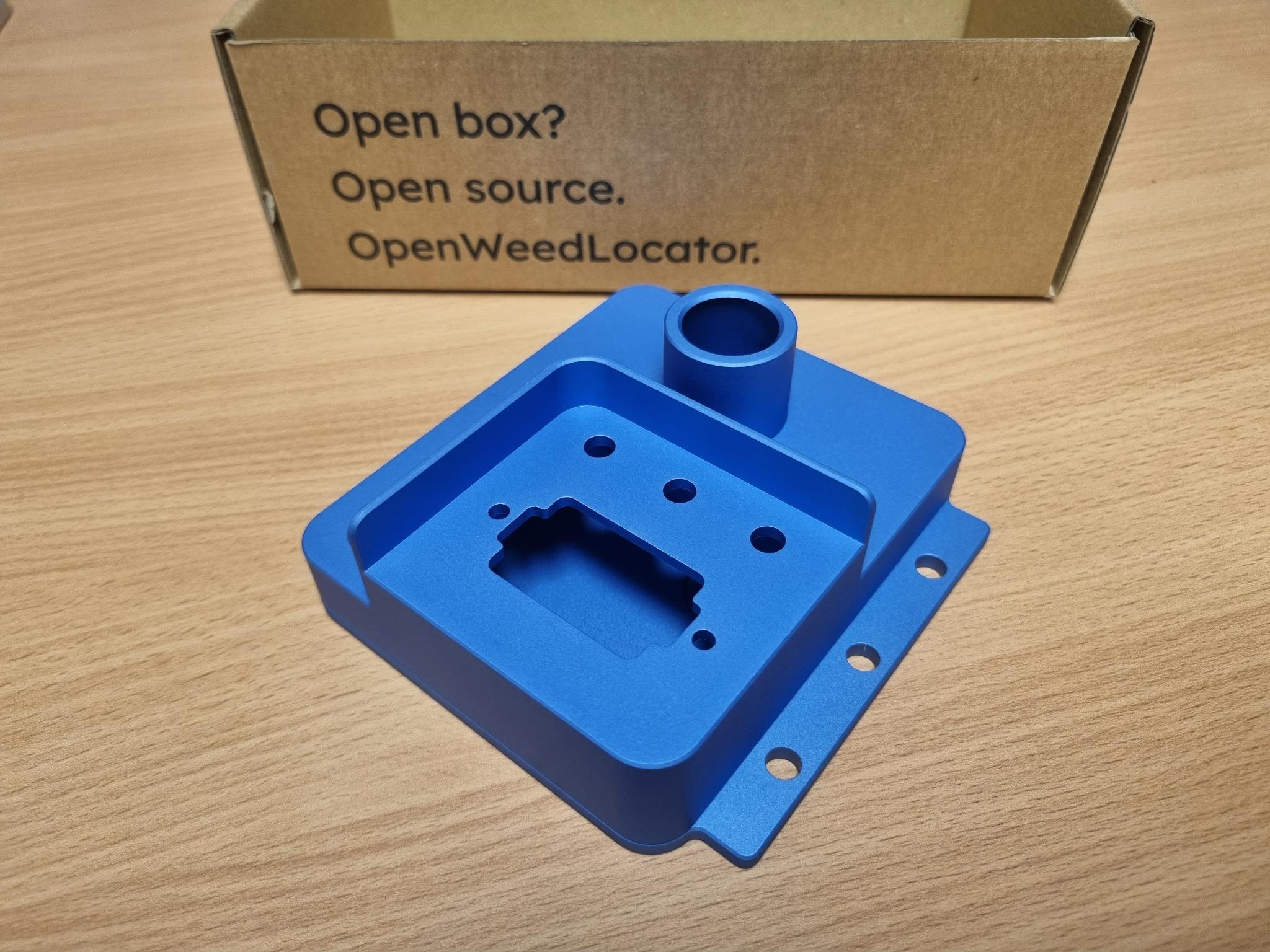
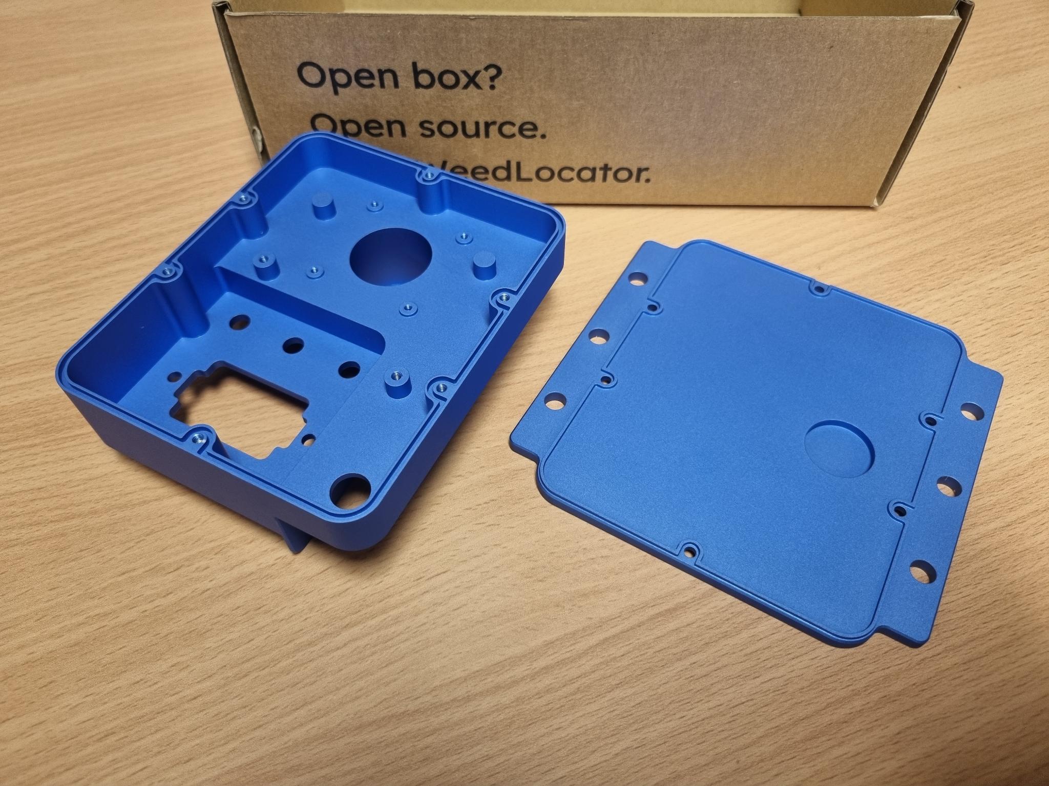
New enclosures arrived today - likely we’ll make some cosmetic modifications and make the front a solid block of aluminium to reduce CNC time and improve robustness. Colour will likely change as well.
Hmm, not too sure off the top of my head sorry! I’m away from the office this week, but I’ll get back to you on the weekend/first thing next week. I’m fairly sure it was the “60 degree” lens off that test pack.